

Before you release final Gerber files, a flexible PCB manufacturer should prove its materials, process limits, bend-reliability methods, inspection plan, and production controls match your design. A low quotation does not establish that fit. Flex circuits combine thin dielectrics, copper behavior, coverlay registration, mechanical movement, and assembly constraints so that a mismatch can remain hidden until the first bend test or production run.
Use the following ten checks as a supplier qualification conversation. Ask for documented capability ranges, examples tied to comparable constructions, and a clear list of assumptions. The goal is to identify manufacturing limits early enough to adjust the stackup, artwork, or test plan without creating a revision after fabrication starts.
The 10 Capabilities to Verify
Before you work through the individual checks, use the table below as a screening framework. Ask the supplier to complete the third column in writing. A manufacturer that answers from process data will do it quickly; a manufacturer that answers from sales material will leave the evidence column thin.
| Check | What to verify | Evidence to request |
| Material and stackup control | Base film, copper type and weight, adhesive or adhesiveless construction, coverlay, stiffener and shielding layers | Stackup drawing with material callouts and finished-thickness tolerances |
| Layer count and copper geometry | Supported layer count for your construction, minimum trace and space, copper weight per layer | Capability table showing minimum geometry for each layer count |
| Drilling, routing and registration | Hole size range, routing tolerance, layer-to-layer registration through lamination and dimensional movement | Process capability data and the method used to control registration. |
| Static and dynamic bend reliability | Whether the circuit bends once during installation or moves repeatedly in service | Bend test method and documented flex-life cycles for comparable constructions |
| Controlled impedance and signal integrity | Impedance tolerance for your specific stackup, not a figure published for a different construction | Impedance model and coupon measurements for the proposed build |
| Coverlay, stiffeners and shielding | Coverlay opening registration, stiffener bonding, shielding attachment, and their effect on assembly flatness | Cross-section sample plus a written process description |
| Surface finish and assembly compatibility | Finish options available for flex, thickness control, and limits for fine-pitch assembly or wire bonding | Finish thickness specification and assembly compatibility data |
| DFM review and file readiness | A flex-specific review completed before the release package is accepted | Written DFM report listing conflicts, missing data and unsupported tolerances |
| Inspection, testing and traceability | Incoming material verification, in-process inspection, AOI, electrical test and lot traceability | Written inspection and test plan with sampling rules and acceptance criteria |
| Prototype and production transfer | Whether the prototype construction reflects the intended production build | Prototype build report and a production transfer checklist |
Material and Stackup Control
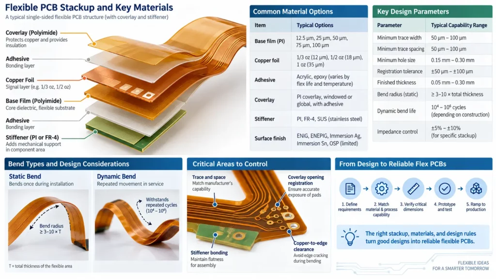
Start with the proposed construction, not a generic material list. The manufacturer must identify the base film, copper type and weight, adhesive or adhesiveless construction, coverlay, bonding film, and any stiffener or shielding layer. Ask whether the materials are routinely stocked and whether substitutions require approval. The stackup must also show finished thicknesses and tolerances. This matters because dielectric thickness, adhesive flow, copper grain, and coverlay buildup affect impedance, bend life, registration, and assembly flatness.
Layer Count and Copper Geometry
Confirm the supported layer count for your exact construction and volume. Then compare your minimum trace width, spacing, annular rings, copper thickness, and copper-to-edge clearances with the supplier’s standard process window. A single minimum value is not enough because achievable geometry changes with copper weight, panel size, layer count, and yield target. Ask which features are standard, advanced, or subject to engineering review, and require the final drawing to identify any exceptions.
Drilling Routing and Registration
Flex circuits need precise alignment among drilled holes, copper, coverlay openings, stiffeners, and the final outline. Review mechanical and laser drilling limits, finished-hole tolerances, via-to-conductor spacing, routing tolerances, and whether laser cutting is available for complex outlines. The supplier must explain how it controls registration through lamination and dimensional movement. For fine features, request a tolerance stack rather than treating each published minimum as independently achievable in the same design.
Static and Dynamic Bend Reliability
Tell the manufacturer whether the circuit bends once during installation or moves repeatedly in service. That distinction drives material selection, copper type, conductor orientation, layer placement, and the required bend radius. Ask how the supplier reviews traces across bend zones, via placement, stiffener edges, and abrupt width changes. For dynamic flex, discuss cycle count, bend angle, temperature, speed, and fixture conditions. A meaningful test plan must reproduce the application’s motion rather than rely on a generic flex claim.
Controlled Impedance and Signal Integrity
If the flex carries high-speed or RF signals, request an impedance model based on the proposed stackup and process data. Verify dielectric thickness control, copper thickness assumptions, trace geometry, coverlay effects, and the tolerance the factory can hold. Ask whether test coupons and time-domain reflectometry are available and how results are reported. Impedance capability must be stated for the relevant construction; a tolerance published for one stackup does not automatically apply to every flex zone or multilayer design.
Coverlay Stiffeners and Shielding
Evaluate the processes that turn artwork into a usable mechanical part. Check coverlay opening registration, adhesive squeeze-out allowances, stiffener materials, stiffener thickness, placement tolerance, and the transition between reinforced and flexible areas. If the design needs electromagnetic shielding, ask about film type, grounding method, and how added layers change flexibility. Connector regions also need flatness and thickness control. These details must appear in the fabrication drawing, not remain as assumptions attached to an email thread.
Surface Finish and Assembly Compatibility
Choose the surface finish around the connector, component, and storage requirements. The manufacturer must explain which finishes are available for flex, their thickness controls, and any limits for fine pitch, wire bonding, repeated insertion, or soldering. Also review panel support, tooling holes, fiducials, carrier methods, and bake or handling requirements for assembly. If the same supplier will assemble the circuit, confirm that fabrication and assembly engineers agree on panelization, paste data, and the stiffener plan before release.
DFM Review and File Readiness
A qualified manufacturer performs a flex-specific design-for-manufacturability review before accepting the release package. Provide Gerber or ODB++ data, drill files, a netlist, stackup, fabrication drawing, controlled-impedance requirements, bend-zone map, stiffener details, panel drawing, and revision identifier. The review must flag conflicting dimensions, missing layers, unsupported tolerances, and ambiguous notes. If your files still need engineering work, PCB design and layout support can help resolve the package before quotation assumptions become production instructions.
Inspection Testing and Traceability
Ask for a written inspection and test plan. It may include incoming material verification, in-process registration checks, automated optical inspection where applicable, dimensional inspection, electrical continuity testing, microsection analysis, and final visual acceptance. Define what is tested on every panel and what is sampled. Lot and material traceability, nonconformance handling, calibration control, and certificate retention are equally important. Review the supplier’s quality assurance overview, then verify the scope and current validity of any certification needed for your market or application.
Prototype and Production Transfer
The prototype route must represent the intended production build closely enough to expose real risks. Ask which materials, equipment, process location, tooling, and inspection steps will change when volume increases. A controlled pilot build can confirm dimensional stability, bend performance, assembly handling, and test coverage before production. Define first-article approval, yield review, change notification, and revision control so that a successful sample does not become an untracked process change later.
Img.Flexible PCB manufacturer evaluation infographic showing material stackup, copper geometry, drilling, bend reliability, controlled impedance, testing, and production capabilities.webp
As one example of the evidence to request, UMEC publishes a flex PCB manufacturing capability table covering materials, stiffeners, layer ranges, drilling, copper-dependent line geometry, electrical test methods, surface finishes, routing, and controlled impedance. Its current page lists one to four layers as standard and five to ten as advanced. Treat any published table as a screening tool: UMEC will still confirm that the complete combination of features in your drawing is manufacturable before release.
Questions to Ask Before File Release
Turn the ten checks into an approval record. Ask the supplier to mark each drawing requirement as standard, advanced, or requiring deviation; identify every material by family and thickness; return a reviewed stackup; state the inspection and electrical-test method; and list unresolved questions. Do not send final Gerbers until both sides agree on the same revision and the manufacturer has documented any exceptions. This short review often prevents more delay than an aggressive fabrication schedule can recover.
How to Score Supplier Answers
Four Dimensions of a Good Answer
Answers are not equally useful. A supplier can reply within the hour with general marketing language, or within a week with data that applies to your design. Score each of the ten checks against four dimensions.
Documented. The answer exists in a specification, capability table, or test report, not only in a sentence inside an email.
Design-specific. The answer references your layer count, copper weight, bend radius, and impedance target, instead of quoting a maximum the supplier reached once.
Verifiable. The supplier can produce the underlying measurement, coupon, or certificate when asked.
Consistent. The answer matches what a second engineer at the same supplier says in a separate conversation.
Then place each of the ten checks on a simple three-level scale.
| Level | What it means | How to proceed |
| Green – documented and design-specific | Written capability data matches your construction | Move to pilot build planning |
| Amber – partial or generic | The answer exists but is generic, or unverified for your design | Request a coupon build or sample before committing |
| Red – verbal only | Answers come from sales material, or written confirmation is avoided | Keep evaluating alternative suppliers |
A supplier that scores green on most checks is ready for a pilot build. Anything that lands at amber should be closed with a coupon build or a sample run before you release production files. UMEC, for example, publishes a flexible PCB capability table you can check against your drawing at the quotation stage, which shortens the back-and-forth on material and geometry questions.
Red Flags That End the Evaluation Early
Some answers should stop the conversation instead of starting a longer one. The warning signs below appear repeatedly in flex projects that fail after release.
No written capability data for your construction. If the supplier can only state limits verbally, there is nothing to hold it to when a panel arrives out of specification.
Bend life claimed without test data. Dynamic flex life depends on copper type, adhesive system, coverlay, bend radius, and layer count together. A number quoted without a construction is not a specification.
Impedance quoted without a stackup. Controlled impedance is a stackup property. A tolerance offered before the construction is defined cannot be verified.
Material substitutions without approval. Flex materials change dielectric thickness and adhesive flow. Substitution without a written approval step moves risk onto your assembly line.
Tolerances described only as typical. A typical figure is not an acceptance criterion. Ask for a specification limit and the sampling rule behind it.
A prototype built on a different construction than production. If the prototype uses a simpler stackup than the volume build, the bend and impedance results do not transfer.
When two or more of these signals appear, the faster path is usually to qualify another supplier rather than to negotiate. A pilot build with a weak process partner costs more than the quotation it appears to save.
Cost and Lead-Time Questions Worth Asking
Flex pricing tracks construction complexity more than panel area, so three questions keep quotations comparable.
Is the quotation based on the same stackup as the prototype? A lower price often hides simpler construction than what you intend to build.
Which operations are performed in-house and which are subcontracted? Coverlay lamination, stiffener bonding, and shielding attachment are the steps most often subcontracted, and they carry the longest lead time.
What is the tooling or setup charge, and when does it expire? Setup is quoted once, and orders can be scheduled months apart so that the second order may carry a surprise.
Comparing flex quotations without these answers usually produces a lower number that does not survive the first build. UMEC quotes flex projects against the submitted stackup so that material, geometry, and finishing steps stay visible in the same document.
Conclusion
A capable flexible PCB manufacturer does more than accept files. It translates electrical, mechanical, and reliability requirements into a controlled construction and test plan. Evaluate the supplier’s evidence across all ten areas, especially bend use, material stackup, feature tolerances, file review, and transfer to production. When the answers are specific to your design and captured in the fabrication package, you can release Gerbers with fewer hidden assumptions and a clearer basis for supplier accountability.
Frequently Asked Questions
What Should I Send Before Final Gerber Files?
Send a preliminary stackup, board outline, layer count, copper weight, minimum geometry, bend-zone drawing, stiffener plan, connector requirements, impedance targets, finish, quantity, and operating conditions. These details let the manufacturer check fit before you freeze the release package.
Can a Flex PCB Be Quoted From Gerber Files Alone?
A supplier may provide a preliminary quote, but Gerbers alone rarely define bend use, material construction, tolerances, stiffeners, impedance, inspection, and acceptance criteria. A fabrication drawing and stackup reduce assumptions and make quotations more comparable.
Is ISO 9001 Enough to Qualify a Manufacturer?
ISO 9001 indicates a quality management framework, but it does not prove capability for your flex construction. Verify relevant process experience, equipment limits, material control, inspection methods, test evidence, and any application-specific certification or acceptance class.
Why Run a Pilot Build Before Volume Production?
A pilot build tests the proposed stackup, dimensional behavior, bend performance, assembly handling, inspection plan, and documentation flow. It also creates an approval baseline before tooling, panelization, or production routing changes increase correction costs.
For a manufacturability review, send UMEC the preliminary stackup, bend requirements, drawings, expected quantity, test needs, and target application. You can contact the technical team to confirm fit and required files before releasing the final Gerber package.